Let’s start with his voice! (Part 8 – It all comes together)

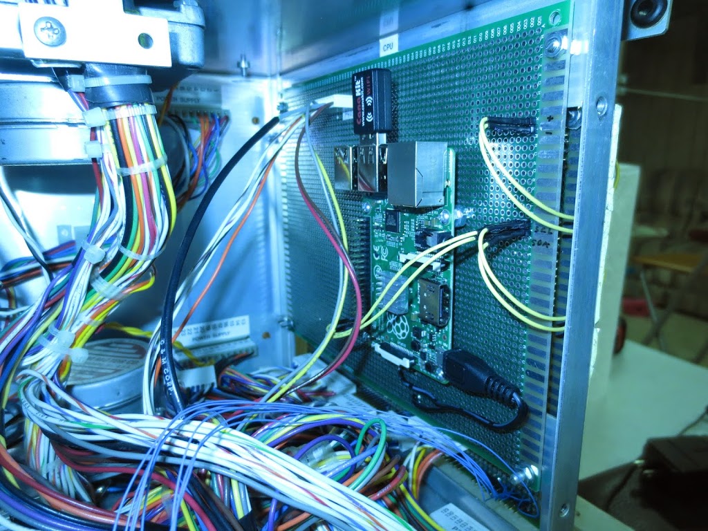
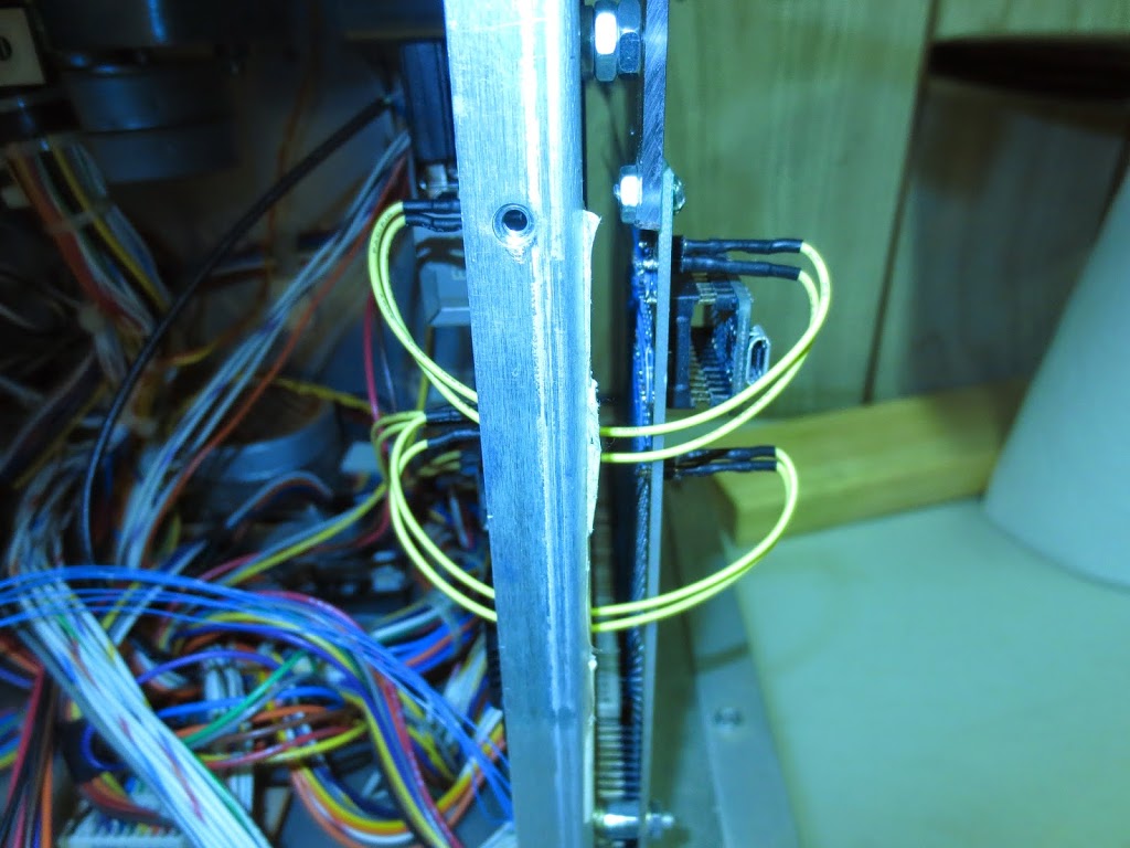
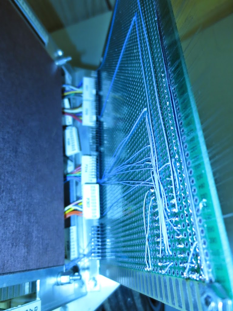
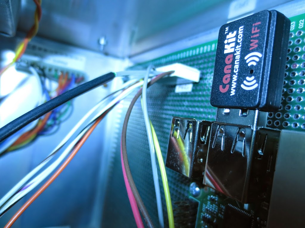
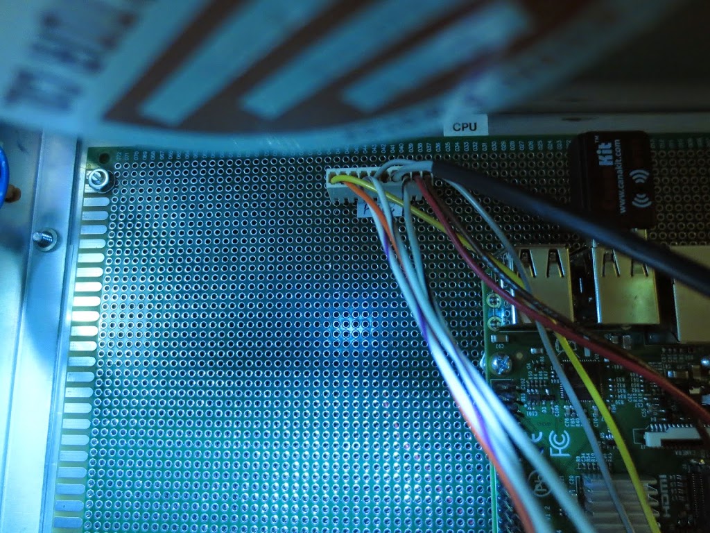
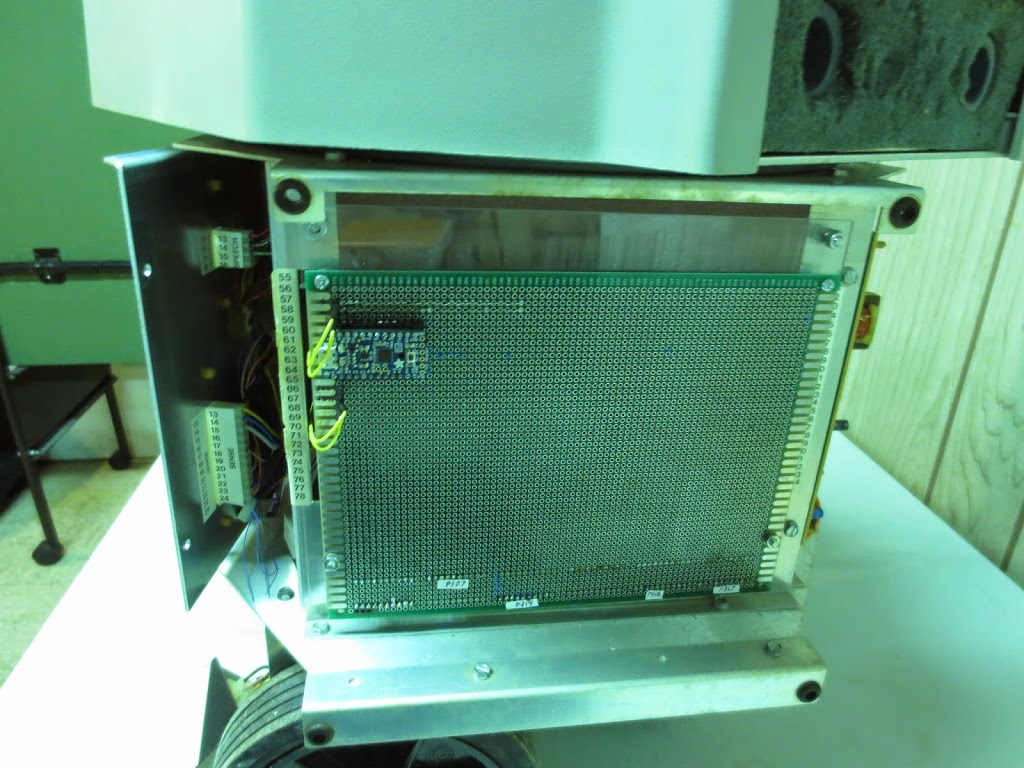
I had ordered 2 of the largest protoboards I could find. Ultimately I’ve decided to mimic the old concept of having the CPU board and I/O board back to back on HERO’s right wall.  Since the largest protoboard I could find fell just short of what I needed, I augmented the difference with acrylic (my wife’s suggestion).  The recent work was relatively light on the programming and relatively heavy on dealing with physical boards, nuts, bolts, wire, and solder.  Although I much prefer the coding, it was a welcome break. 

I/O board with trinket installed via IC socket mounted where the original I/O board once was
Raspberry Pi mounted inside of HERO, where the original CPU board once was.  On the right, you can see the power cables (top) and I2C cables (bottom) running form the CPU board to the I/O board.
Power (top) and I2C (bottom) lines running between CPU and I/O boards
The back of the I/O board. (looking down from above HERO)
HERO now has WiFi capabilities! Although I was ready to pipe the dongle to a place outside of the metal it seems to be working great inside the shell… go figure.
This is where the CPU board gets its power and some basic interrupts

Leave a Reply

Your email address will not be published. Required fields are marked *