Onward! Let’s make this thing move! (Part 3 – Now how do I make it stop??)
Alright, so it has admittedly been nearly 3 years since I posted anything here! Crazy how time flies! Good thing HERO doesn’t age, he just… matures. It wasn’t until just the last couple of weeks that I got back involved with him and discovered I had missed a critical component of his drive. The ability to have him go for a set distance!
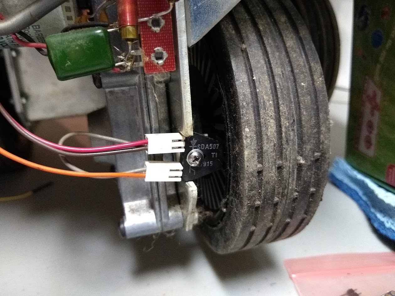
This is accomplished by an encoder disk on the drive wheel and an IR photodiode and phototransistor. Up until this point, I had become relatively accustomed to blindly assuming that the control boards that HERO’s IO board used to connect to would handle most of the heavy electrical stuff and that everything was basically reduced to signal voltages. So when I looked at the pinouts for the phototransistor/diode, I saw 3 pins, “5 volts”, “ground,” and “disc signal.” Naturally, I hooked up the “disc” to an input IO port on the Arduino, “5 volts” to a 5-volt source from the circuit and ground to the ground block. Unfortunately, I wasn’t getting any value at all on the input pin. I then broke out the circuit onto a breadboard, and as I went through the specs on the TIL139 sensor I could find from 1979 (https://pdf.datasheet.live/5964db27/ti.com/TIL139.pdf) and analyzed my circuit more closely I realized that I should have had a resistor as I was putting the full current of the circuit through a device designed for 40ma. As there was no control board, I had expertly fried the optical sensor.
This wasn’t immediately apparent, however, as I also didn’t have the circuit grounded correctly at the time, causing both capacitive touch noise to the circuit as well as noise introduced from a florescent light overhead. This gave the illusion that as I intentionally blocked or reflected the light, I was having some effect on the circuit when measured on a voltmeter. Once I realized that I had likely blown out the component, I was able to test the phototransistor side with a remote control to see how the circuit should have been affected.
I found a site that sold a replacement part – https://www.electronicsurplus.com/texas-instruments-til139-house-source-sensor-reflective-assembly-sda507 and ordered 2 of these figuring I’d likely blow up another before I had this solved.
Once the new components arrived, I did my best to match my interpretation of the spec. Specifically, the spec called for 1.5 volts and 40ma. I worked out a voltage divider to bring it to 1.5 volts down from 5 and was honing on getting the current down to 40ma when I realized that the 1.5 volts were voltage drop across the diode. I went back to a 5-volt source, and Ohms law gives 3.5 volts / 0.04a = 87.5ohm resistor. Changing that to a 100ohm resistor would change the current to 35ma, which was perfect. I then confirmed this using assorted colored diodes with various voltage drops. Now, without fear of burning out my diode, I was able to hook up the diode and confirm it was indeed lit using my cell phone camera (A handy tool when looking for IR).
Now the photodiode was confirmed to be working, but the phototransistor and getting the appropriate signal back to my Arduino became the new challenge. I set up the analog input pin of my Arduino to graph the voltage and built the following circuit:
The funny thing was I thought the meter was set up to measure current, not voltage – so I didn’t realize I had built the above circuit. It appeared to be working correctly, as any reflected IR light would change the voltage from ~0V to ~2.5V. This was enough of a clean jump that I could accurately count the signal on the Arduino. Then I realized the mistake I had made with the voltage meter and switched it to measure current. The circuit effectively died. The voltage spike from the light dropped to about 0.1V and barely at that. Took me a couple minutes to realize what was going on, but the voltmeter was effectively acting as a large pull-down resistor. I Then tried substituting the meter with a 10K ohm resistor pot. The circuit remained dead. I realized that the pull-down was overpowering the very high resistance of the phototransistor and acting as the path of least resistance. I checked the impedance of the voltmeter and determined it’s about 10M Ohms. I substituted a 10M ohm resistor for the voltmeter, and the circuit came to life!
Finally, I just needed to clean up my breadboards (cause the diagram above looks so clean and straightforward compared to reality) and finalize some code on the Arduino and expand the Raspberry Pi driver library I wrote for controlling the motor board.
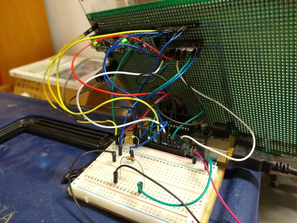
In the below video, you can see the wheel is powered and the Arduino graphing the voltage coming out of the encoder.