Let’s start with his voice! (Part 7 – HERO speaks!)
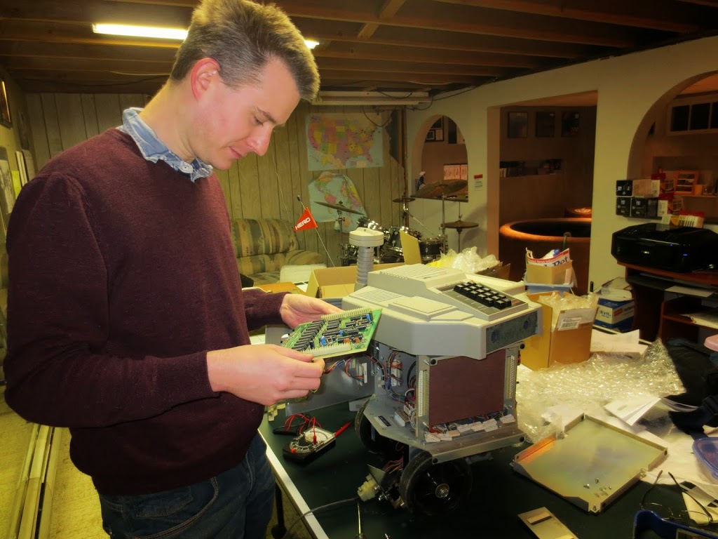
After re-installing the speech board, which has been a source of endless entertainment over the last couple weeks, back into HERO, I then had to figure out how the Trinket Pro will integrate into HERO’s circuit.
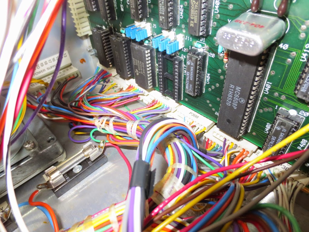
I opened up HERO and stared at the mess of cables (pictured below), trying to figure out where to start.
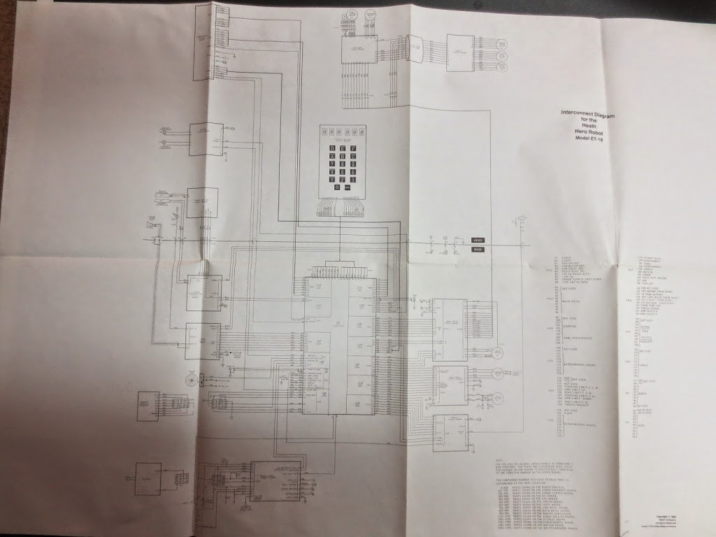
Fortunately, I still have all of his schematics, and so traced through where the pins for the speech board end up.
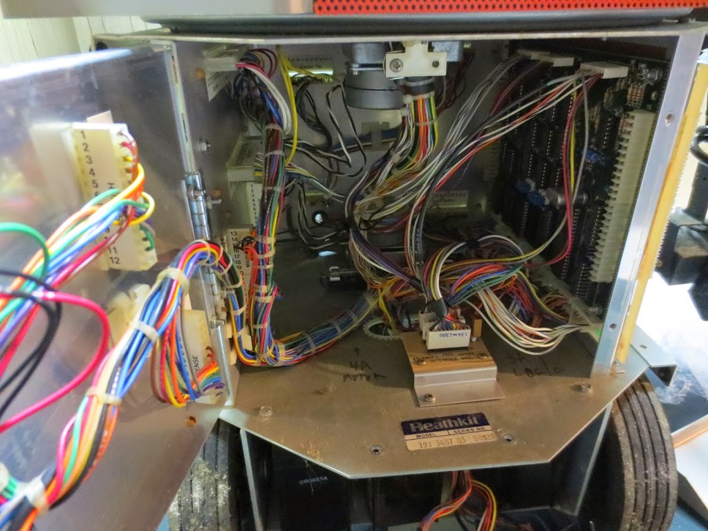
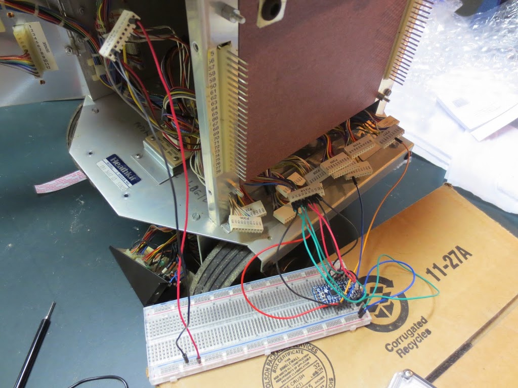
Turns out, there are four plugs of 10 pins each that plug into the I/O board that each has something to do with the speech board. The phonemes and pitch seem grouped together on one plug, but the A/R, Strobe, and Power each come from a different pin. His main cavity is a rather tight space to work in. As I didn’t yet have the nerve to pull out his I/O board, I attempted to pull out just the plugs I would need for his speech. As per the graphic below, not an easy task:
The specific connections I needed were difficult to remove, couldn’t reach outside of his body – or even to a spot where I could efficiently work on them, and even more challenging to plug back in. I decided the best course of action would be to remove the I/O board – not a light decision in that it may be tough to go back from this point. This became clear as some of the connectors were offset on the pins they connected to, and I hadn’t noticed until I had removed most of them. I pulled out all the connectors one by one and then finally removed the I/O board. The I/O board plugs into the CPU board by a series of connector pins on the left and right side that fit (quite tightly) onto pins extruding from his chassis. The other sides of the pins are connected to the CPU board in the same fashion.
Now for the question of connecting my Trinket Pro. Ultimately I will need to find the male counterpart to the connectors, and knowing this, I started doing some research. The pins looked small and with a spacing that might be about the same as a standard breadboard (2.54mm). Feeling hopeful, I grabbed some male header pins and viola! They fit!!! This gives me a great direction as I begin to assemble a final I/O board (previously I called it an interface board, but have decided to adopt Heath-kit’s nomenclature) sometime soon.
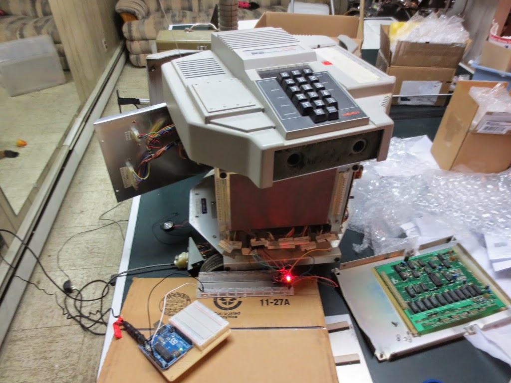
Back to the task at hand, it was “simple enough” to follow the schematic and find the correct connectors for the speech board. From there, I test wired the Trinket Pro into the mix using a breadboard, wires, Arduino for 5V logic power, and some (a lot of) hope. At this point, I couldn’t find any 5V leads and had momentarily forgotten that the Trinket or the Arduino would be capable of pulling HERO’s 12V power down to the 5V I needed for logic. Instead, I plugged the Arduino into the wall (via DC converter), used that to power the Trinket Pro, and plugged HERO into the wall using his charger to power his main systems (or the ones that power could still reach without an I/O board plugged in). I crossed my fingers, flipped the switch, and expected to hear nothing. Instead, what I heard was this:
Essentially a low pitch hum. It sounded like 60 Hz, but the speech chip changes waveforms and makes it very difficult to know if it was a 60Hz hum or not.
After a bit of tinkering, I got what sounded like the beginning of a word.
A bit more tinkering, and it occurred to me that maybe the fact that I was providing my own voltage and ground external to HERO’s could be the issue. I then pulled from the 12V used by HERO to power the speech amp and hooked that into the VIN of the Trinket Pro. Likewise, with the ground. At this point, my Trinket Pro was isolated from the wall socket as well as the Arduino.
The next test went something like this:
SPOILER ALERT – IT WORKED!!!
A little more digging in the specs for where to hook it up more permanently in the future than the speaker eventually led me to a power supply to the CPU board and 5V to boot! I made a final alteration for the night by sourcing my power from there and called it a night.
So, while there’s more to do with the speech portion, I believe the next step is to begin to integrate the Raspberry Pi into the mix. One small challenge for anyone who works with electronics, but moderate challenges for me at the moment is to derive a voltage divider that takes the 5V logic and turns it into the 3.3V needed.
Let the games begin!