Let’s start with his voice! (Part 6 – Minifying the circuit)
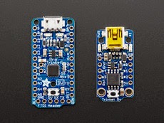
So, plan A was to order a 5v Trinket Pro from adafruit, but apparently, I accidentally ordered a 5v Trinket instead. The main difference is that the Trinket has 5 GPIO pins, while the Trinket Pro has 18!! GPIO, as well as 2 extra analog inputs, 28K of flash, and 2K of RAM.
| ||
| Trinket Pro on the left, Trinket on Right |
I currently need 11 GPIOs for communication with HERO’s speech board, and an additional 2 for setting the chip up as an I2C slave. So wanting to find a way to make it work without waiting for the Pro, I started down the path of shift register integrated circuits (ICs). The problem was I only had 1 shift register. I built what I could for the night and, assuming it was still 1980, and RadioShack was relevant, figured I’d pick up an additional shift register in the morning and figure out how to daisy chain them together. Of course, RadioShack didn’t have what I was looking for, and so I ordered a bunch of shift registers, as well as the 5v Trinket Pro, online. Once everything arrived, I guess I thought, “Hey, let’s make this circuit as complex as possible.” Rather than migrating over to the Trinket Pro, I worked through getting the daisy chain shift registers to work with the Arduino Uno so I could minify and still use the Trinket, saving my Pro for “something else.” Daisy-chaining had its difficulties – the most significant being that, much to my surprise and naiveté, although I could find library calls to “shift in” bits form a shift register… you need special shift registers to do this. My standard SN74HC595N is apparently are not magical enough to do this… This means I need a separate input pin reserved for the acknowledgment signal that the SC-01-A sends. So to run this circuit using 2 shift registers in serial (each shift register has 8 outputs, and I need 10), I need:
- 1 data pin (shift register)
- 1 latch pin (shift register)
- 1 clock pin (shift register)
- 1 SDA pin (I2C)
- 1 SCL pin (I2C)
- 1 Input Pin (acknowledgment from SC-01-A)
So yes, if you’re keeping score.. that is 6 pins that I require.. and the Trinket only has 5. It’s about now that I began wondering why I was working so hard to do this using shift registers and a trinket instead of just using a trinket pro. The answer seems to be “cause I thought it’d be cool.” Clearly, I have a somewhat twisted perception of “cool“… that probably would explain a lot. In any event, Trinket Pro it is!
Moving to the Trinket Pro
So this was interesting. I rarely solder; however, step one of using the Trinket & trinket pro is to solder the pins onto it. Aside from having overdone it with the flux a little, then working on getting the excess flux off with an old toothbrush and being left with a mildly fluxy, mildly minty trinket pro, the soldering couldn’t have gone better! I ported the code, though it seems I don’t have pin 2 and pin 7 available on the Trinket Pro, and so I needed to make some mild adjustments to my code to support that. Additionally, I am not using the I2C slave code just yet. Instead, for testing purposes, I hardcoded a simple phrase. After uploading the revised program to the Trinket Pro, disconnecting the USB from the Pro, and instead of grabbing the requisite 12V from a wall charger plugged into my Arduino (solely for Vin), I have a functioning microprocessor, much smaller than an Arduino, doing precisely what I want (at least for now)! Check out the video: